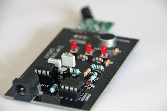


Clap sensor circuit PCB (soldered).
Clap sensor PCB bottom, soldering.
Clap sensor circuit PCB (soldered).
Circuit diagram for PCB (made before adding extra capacitor).
Test: sensor set up on breadboard.
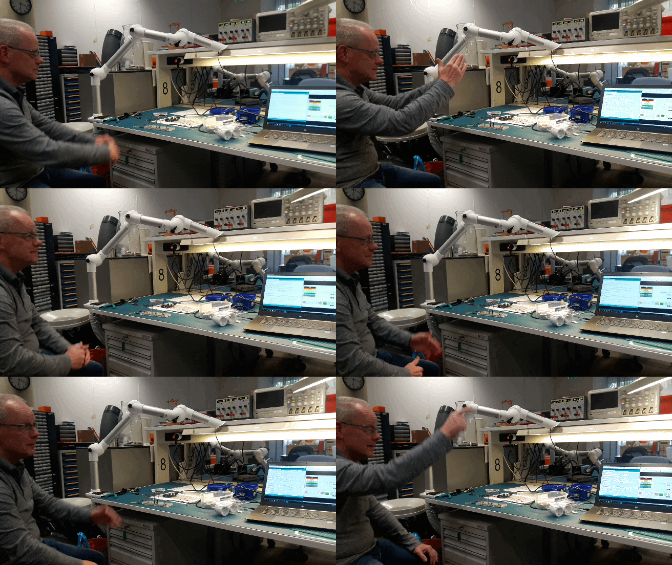
Mini demo: One clap turns on light (upper left).
PCB design
With this clap sensor devices in house can be turned on or off by clapping various patterns, resulting in a playful interaction with devices in the house. Three different clap patterns turn off and on three sockets.
The clap sensor is based on the clap sensor design ‘d.search’ coaches Jan Rouvroye and Geert van den Boomen used for a workshop and is optimized for clapping sounds using capacitors to ‘cut off’ the sound at the appropriate frequency. Other capacitors are used to stabilize the current and minimize interference of small current changes on the circuit. The resistors placed over the microphone and the opAmp are meant to create a reference current. At the microphone this is done by means of dividing the current into two creating one current influenced by the microphone input and one reference current. By means of RFID technology the clap sensor connects to an existing system of ‘Klik-aan klik-uit’ sockets and it turns these sockets on or off. The onboard LEDs are used to indicate which sockets are turned on or off.
Find out more: Why design a PCB and Calculations
I believe circuit and PCB design is an important aspect of realizing prototypes and communication with other engineers, and therefore it is a good skill to have (at least the basic) knowledge of and experience in. Actually ordering and soldering the PCB was of great value. Next time, for instance, a ground-plane is necessary when working with RFID technology as it is easily influenced and easily influences the rest of the circuit due to peak current.
Initially I opted for integrating a clap sensor into a lamp. More specifically into a socket for a lamp. This would require me to ‘play around’ with the 230V power supply in the PCB design. As she was strongly advised not to, by experts, she decided to consider other options; finding an even better one: controlling multiple existing sockets with a sensor.
I designed and ordered the PCB and made calculations regarding its use of current. After soldering the ordered PCB’s I needed to add to components to make the connection to the RFID chip less sensitive for in circuit interference. The RFID technology requires peak current and, with this current, influences the LEDs in the current circuit. The breadboard already filtered out these peak currents due to its own standard resistance; therefore this was not noted before. The second addition, to solve this same problem, was to make the sensor even less influenceable by non-clapping sounds: another capacitor which influences the ‘cut off’ frequency.
It was calculated that a 10000mAh powerbank could power the sensor, taking into account heat loss and quality loss of the powerbank, for ±14 days which makes the sensor very energy effective. Nevertheless it was not taken into account that a powerbank requires a minimum current use for it to stay on. Thus the sensor cannot make use of a every powerbank as it requires too little power.
Calculations
Led light (red) 4.7 mA (because I aim to achieve little current usage, 20mA is normal)
Forward voltage red led = 1.8 V at 5V (looked up in datasheet)
I = V/R with a 680 Ω resistor and a 5V power source this results in) I = (5-1.8) / 680 = 0,0047
Microphone circuit, in a microphone I is negligible as it has extremely small changes. R= 100R + 10K + 10K = 100 + 10000 + 100000 = 20100Ω
I = 5 / 20100 = 0,0002488 = 0,25mA
ATTINY 85 power consumption at 5V, 20MHz (in the most unfavorable situation) taken from datasheet = ± 11,5mA
Power consumption LM358 from datasheet: ±28nA, this is such a small amount that it is negligible.
The RF module, FS1000A operates on a 5V current. The output power is 22mA. In theory thee is no current when in rest but earlier people experienced a rest current of max. 4mA. The same as for the receiver. (Taken from Arduino forum) To be certain 4mA is used in the total calculation.
The capacitors only draw a little current once, to charge. This is negligible in the total amount.
In rest the sensor draws: I = 4mA + 11,5mA + 0,25mA = 15,75mA.
When all sockets are turned on there has 3 times been a peek of 33,75mA after which a led turns on and a varied current between 15,75 and 29,85 mA starts. (15,75+(3*4,7))
Let’s say the sensor is on half of the time and 1 or more devices are on (not always all are on). 1/2(3*4.7) = 7.05mA.
Half of the time all devices are off (during the night for instance) so 15,75mA + . 1/2(7.05)mA = 19,275mA as typical consumption.
A 10000mAh powerbank is an often occurring powerbank. With such powerbank the system works approximately 10000/19,275 = 518,8 = ±518 hours = 21 days.
Therefore it is not necessary to continuously plug the sensor into a socket. Even when 20% of the power is lost to heath and the powerbank drops ±10% in quality the sensor still can be employed using the powerbank for ±14 days.
OVERVIEW
Course:
-
Coach:
Jan Rouvroye (TU/e)
Geert van den Boomen (TU/e)
Competences:
Technology & realization
Key learning points:
Datasheet usage, circuit calculations, PCB design
Timeframe:
April 2017 - June 2017